Rehousing the Philips SPC900NC
I picked up a project box from Maplin to rehouse my SPC900NC. I thought it would be a step towards adding some sort of cooling.
Well I’m pleased to say the whole process took no more than an hour and I’m very happy with the results. I took some photos so that you can see how I did it.
STEP 1
Remove the boards from inside the camera
 Pop the case open by removing the side covers then insert a screwdriver into the clips to unlatch them. Remove the elastic bands that hold the two halves of the inner shell together.You need to remove the 2 bigger screws to seperate the two boards, then remove the two smaller screws, not the ones holding the lens holder in place, to remove the boards from the plastic enclosure.
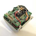
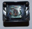
You can see the wires that I use for the LX mod soldered onto the boards in this view. The black and red wires are power from the USB connector and the orange wires are the PIN 13/PAD 13 connections for the LX mod. The blue wires are not used in this mod, but can be connected to a switch to allow the camera to be switched between LX and normal modes. Disconnecting the parallel port cable from the PC will also return the camera to “normal” mode, so I didn’t bother to fit a switch.
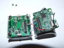
 This is a view of the boards after the camera housing has been completely removed. I had bought some 2×10 IDC headers to connect the two boards side by side, but the connectors are not standard sizes and I wasn’t able to do this. Mounting the boards side by side would make it easier to add cooling so I may do this at some point by soldering ribbon cable between the two boards.
STEP 2
Prepare the project box
Drill a hole in the middle of the lid or back of the box, I chose the back of the box so that the lid can be removed without disturbing the wires. I use a small drill bit to start the hole then a 12mm hand held reamer to enlarge the hole to take the threads of the eyepiece adapter.
Drill holes for the wires. I drilled these near the top edge of the box allowing me to drop the cables in rather than remove the connectors and thread the wires through the holes. Use some side cutters to trim the top of the holes and finish off with a file to make sure there are on sharp edges to cut into the cable.
I had trouble removing the USB cable from the camera housing. It looked like the gromit could be turned 90° and slipped out, but I couldn’t move it and instead cut the case with some wire cutters. There’s no going back now!
STEP 3
Assemble the camera
 Use the eyepiece adapter to thread through the box and into the threads on the lens mount attached to the bottom board. Don’t overtighten it but make sure it’s firm, this is all that holds the boards in place.
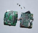
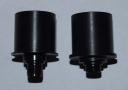 You don’t need to use the long reach eyepiece adapter now, infact I was concerned that if I tightened it up it may press against the CCD, so I swapped it for a standard adapter as seem on the right in this image. The long reach adapter is recommended for the SPC900NC while it’s in the original case
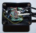 All the cables are reattached, note the holes in the box to allow the cables to pass through. The gromet and strain-relief sleeve on the CAT5 cable is for my peace of mind as I was concerned the stiff wires would break when the mount slews.
 The finished camera.
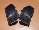
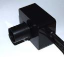 A view showing the cable exit points.